Voids in Composites: Causes, Measurement and Control
Voids in Composites: Causes, Measurement and Control ! Voids visible in a composite laminate cross-section A void in a composite is a three-dimensional region left unfilled by resin and fiber.
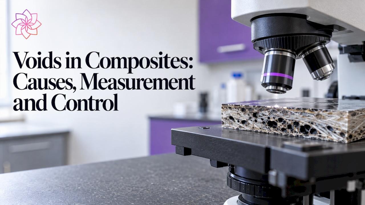
A void in a composite is a three-dimensional region left unfilled by resin and fiber. Voids come from air or volatiles trapped during impregnation, lamination or cure, and they reduce interlaminar shear strength, fatigue life and transverse properties even at low volume fractions. Controlling them is a joint problem of process (pressure, temperature, cure cycle) and of resin chemistry (viscosity, wetting, air release). Formulators who qualify the liquid resin system for air release and low foam before it reaches the laminate remove one of the most controllable sources of porosity. ASTRA Chemical supplies silicone and non-silicone defoamers and dispersants, with technical support, for this stage of formulation.
TL;DR
- Voids are unintended pores, usually entrapped air or volatiles, present in nearly all fiber-reinforced composites and classified by size, shape, location and distribution.
- Formation is governed by resin viscosity, processing temperature, cure cycle, pressure and time, and by the competition between capillary and viscous flow at the fiber and tow scale.
- Acceptable void content depends on the application: about 2% is the usual ceiling for critical aircraft primary structure, and every additional 1% can cost 5 to 10% of interlaminar shear strength in unidirectional carbon/epoxy.
- Micro-CT, acid digestion, optical microscopy and ultrasonics each answer a different question, so the method must match the decision being made.
- Air entrained in the resin during mixing and handling is a formulation-controlled contribution to voids, and it is addressed with defoamer and dispersant selection and dosage.
A void, or pore, is a region of the laminate that contains neither matrix nor reinforcement. The 2019 review by Mehdikhani and colleagues describes porosity as small resin voids or air bubbles, and distinguishes surface porosity from bulk porosity, and porosity within tows from porosity between tows.
Four characteristics define a void population and determine how much damage it does:
- Content: the volume fraction of voids in the laminate, normally reported as a percentage.
- Shape: spherical or equiaxed pores behave differently from elongated, needle-like or crack-like voids.
- Size: large pores act as individual flaws, while a fine dispersion of micro-voids affects the matrix more diffusely.
- Location and distribution: voids between plies or at fiber-matrix interfaces are generally more damaging to interlaminar properties than isolated pores inside a resin-rich region.
A 2025 nondestructive-testing paper by Walter, Beausoleil and Arès, summarized in a U.S. Department of Transportation repository, classifies voids by bounding box: needle-shaped voids are shorter than 20 μm, while equiaxed voids exceed 500 μm in length, exceed 50 μm in width, or have a length-to-width ratio below 3. This distinction matters because the same void percentage can describe very different defect populations.
Voids versus other composite defects
Voids are one defect class among several. A composites engineering webinar lists under-cure, delamination, fiber misalignment, dimensional errors, and machining, assembly and handling errors separately from porosity. The distinction is practical: a void is a missing-material defect created during processing, while delamination is a separation between plies that voids may nucleate but that has its own causes, such as impact or interlaminar stress.
How voids form
Air and volatile entrapment
The 2022 study by Elkolali and coworkers reports two principal routes. The first is incomplete displacement of air from fiber surfaces while the resin coats the reinforcement. The second is entrapment of air or volatiles during lamination, particularly in filament winding. The same study identifies resin viscosity, processing temperature, cure cycle, pressure and time as the factors that govern the resulting porosity.
The sources of trapped gas fall into three groups:
- Mechanical air: air carried in with dry fabric, folded into prepreg layups, or left between plies and at tool corners.
- Dissolved or entrained air in the liquid resin: air introduced during mixing, pumping, degassing and transfer, which persists as microbubbles in viscous systems.
- Volatiles: moisture, residual solvents, reactive diluent fractions or reaction by-products that vaporize as temperature rises during cure.
Why the scale of the flow matters
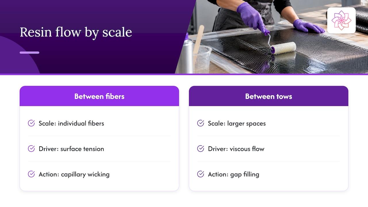
A 2023 to 2024 study on manufacturing laminates with controlled void content frames void formation as competing flow physics. Between individual fibers, surface tension dominates and capillary pressure drives resin wicking. Between tows, where the spaces are larger, viscous flow fills the gap. Because the two mechanisms advance resin at different speeds, one can leave air behind the other. The capillary number, which combines resin viscosity, flow velocity, surface tension and contact angle, is therefore the key design parameter for minimizing voids.
For a formulator, three of those four variables are properties of the resin system: viscosity, surface tension and contact angle against the fiber sizing. This is where additive selection enters the discussion.
What voids do to mechanical performance
The effect of voids is well documented and consistent in direction, though the magnitude depends on the laminate and the property tested.
- Interlaminar shear strength: porosity in fiber-reinforced composites can considerably degrade interlaminar shear strength, a property dominated by the matrix and the interface.
- Shear strength and fatigue in unidirectional carbon/epoxy: the 2025 paper cited above reports, citing Mehdikhani et al. (2018), a 5 to 10% drop in interlaminar shear strength for each 1% increase in void content, and up to a tenfold decrease in cycles to failure at 2% void content.
- Stress concentration: Elkolali et al. describe voids as stress intensifiers and cite a stress-concentration increase of up to 1.85 near void edges.
- Transverse properties: a 2016 modeling study by Dong found that in its modeled carbon-fiber/epoxy system each 1% increase in void content reduced transverse modulus by 1.5%, and identified about 2% as a critical void content for transverse strength.
These figures come from specific material systems and models. They indicate the direction and rough order of magnitude of the effect, and each application needs its own qualification data.
What void content is acceptable
There is no universal acceptable value. The limit follows the consequence of failure and the property that governs the design.
| Application context | Typical void guidance | Source basis |
|---|---|---|
| Critical aircraft primary structure | Tolerated porosity usually around 2% | Walter, Beausoleil and Arès, 2025 |
| Aerospace composites made by VARTM | Void fraction below 2% desired; modified processes reached below 2% in unidirectional fabric and typically below 3% in biaxial fabric | NASA, 2010 |
| Industrial, marine, wind and general-purpose laminates | Set by the customer specification or internal qualification, based on tested property retention | Application-specific |
For coatings and adhesive manufacturers supplying resin systems into composite fabrication, the practical consequence is that the resin must allow the fabricator to reach the customer's void limit with a robust process window, not only under ideal conditions.
How void content is measured
Each measurement method gives a different type of information, so the choice depends on whether the question is a number, a location, or a pass or fail decision on a part.
| Method | What it gives | Main limitation |
|---|---|---|
| Acid (matrix) digestion | Fiber, matrix and, by calculation, void percentages | Destructive; no information on void shape or position |
| Optical microscopy | Void size and shape in a section | Two-dimensional; requires sectioning and polishing |
| Micro-computed tomography (micro-CT) | Three-dimensional void position, size and shape | High-resolution scans are limited to small specimens |
| Ultrasonic testing | Nondestructive screening of parts via attenuation | Needs calibration against reference coupons of known void content |
The Elkolali study compared digestion with micro-CT: micro-CT delivered more consistent void detection and actual void locations, while digestion measured fiber and matrix percentages better. A 2019 study on CT segmentation thresholds confirms that digestion is destructive and does not reveal morphology, that optical microscopy is two-dimensional and needs sectioning, and that micro-CT is a three-dimensional, nondestructive method constrained to small specimens at high resolution. The same study shows that the segmentation threshold chosen for the scan affects the reported void content, so thresholds should be fixed and documented when results are compared between batches or suppliers.
For aerospace parts, the 2025 paper reports that ultrasonic testing is preferred for void quantification. Micro-voids scatter rather than reflect the beam, so porosity appears as attenuation of the back-wall echo plus increased noise, and empirical porosity curves built from coupons with controlled void percentages link attenuation to void content for a given material.
A workable qualification plan for a new resin formulation uses digestion or micro-CT on small panels to establish the void baseline, then relies on ultrasonic or optical checks for routine production monitoring.
Reducing voids: process variables
The process levers follow directly from the formation mechanisms.
- Viscosity at impregnation: a lower viscosity during the infusion or impregnation window improves flow into tows, but too low a viscosity can increase run-off and resin-starved zones. The target is a viscosity that matches the flow velocity, which is the capillary-number logic described above.
- Cure cycle: NASA's 2010 high-temperature VARTM report found that lowering the cure temperature, extending cure time and staging the cure reduced void content in the resin systems tested. Slower, staged heating allows volatiles and entrapped air to escape before the resin gels.
- Pressure and time: sustained compaction pressure holds gas in solution or collapses it, and adequate time under vacuum allows removal before gelation.
- Material conditioning: dry reinforcement and degassed resin enter the process with less moisture and less entrained air.
- Data feedback: void rates vary with shift, tool, material lot and ambient conditions, so tracking quality and process data by batch reveals which variable drives the defect. A manufacturing process improvement guide describes how real-time performance and quality monitoring supports this kind of root-cause analysis on the shop floor.
Reducing voids: the resin formulation
Process control cannot compensate indefinitely for a liquid system that arrives at the tool already carrying microbubbles. Three formulation areas deserve attention.
Air release and foam control
High-viscosity epoxy, polyester, vinyl ester and polyurethane systems hold entrained air for long periods because bubbles rise slowly. Foam generated during high-shear mixing, pumping or filling can carry through to the laminate as spherical voids. Defoamers are used to promote bubble coalescence and release at the surface. Silicone-based and non-silicone defoamers differ in how they interact with the system: silicone types are efficient at low dosage in many resin media, while non-silicone types are selected where surface-tension effects or compatibility with later coating, bonding or finishing steps matter. Dosage requires care in both cases, since the effective range is set by the resin, the mixing energy and the temperature, and an unsuitable choice can create surface defects instead of removing bubbles.
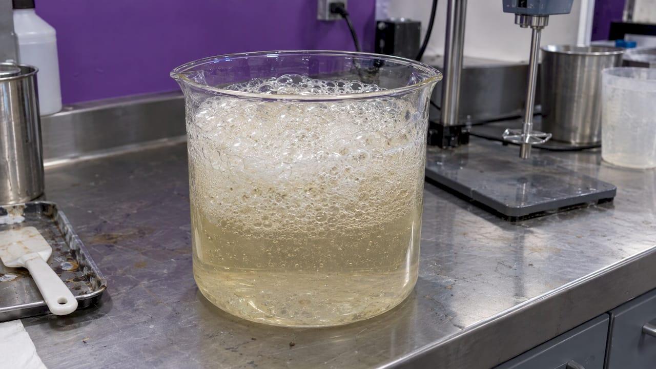
The ASTRA DF® and ASTRA DF NS® product lines cover the silicone and non-silicone options respectively, and ASTRA Chemical provides technical support for matching a grade and dosage to a given formulation.
Dispersion of fillers and pigments
Filled and pigmented systems add a second source of trapped air: agglomerates of powder carry air in their interstices, and poorly wetted particle surfaces hold air that is released only slowly. A dispersant that wets the particle surface and stabilizes the dispersion helps displace this air, lowers the viscosity of the filled system for a given loading, and reduces the viscosity spikes that complicate impregnation. Lower and more stable viscosity moves the system toward a better capillary number. ASTRA DISP® is the dispersant line for this purpose.
Rheology and reactive components
Rheology control must balance two goals: enough structure to prevent sag and filler settling, and low enough viscosity at the processing shear rate to impregnate fibers completely. Rheology modifiers are therefore evaluated at both low and high shear. Reactive diluents lower viscosity and, unlike solvents, become part of the crosslinked network, which reduces volatile release during cure; their terminal groups and dosage determine the effect on cure and final properties, as discussed in the ASTRA CHEMICAL guide to reactive diluents and functional additives.
A qualification routine for formulators
A practical sequence for evaluating a resin or additive change against void performance:
- Fix the baseline: record resin viscosity versus temperature, gel time, and the void content of reference panels made with the current system.
- Measure air content and foam behavior of the mixed resin, with and without the candidate additive, at the dosage range proposed.
- Produce panels under the production cure cycle and, separately, under a staged cure to see how much margin the formulation has.
- Quantify void content by one consistent method, with the same segmentation threshold if CT is used.
- Test the property that governs the application, such as interlaminar shear strength, transverse tensile strength or fatigue life, to confirm that lower void content translates into retained performance.
- Check secondary effects: cure kinetics, glass transition temperature, surface appearance and adhesion to later layers.
Perspective
Voids are most often discussed as a lamination problem, yet a share of them is decided before the resin touches the fiber. A resin that carries microbubbles or whose filler loading drives viscosity beyond the infusion window will produce porosity regardless of how carefully the cure cycle is staged.
Our approach to additives for composites and related coating and adhesive systems starts with the liquid system: air release and foam control with silicone and non-silicone defoamers, filler and pigment wetting with dispersants, and viscosity behavior across the shear range. Each of these is meant to widen the process window the fabricator works in.
We support qualification with laboratory work and dosage guidance, because the right grade and the right amount depend on the resin, the mixing energy and the temperature. Our batch consistency and documentation are designed to make a qualified formulation repeatable from one production lot to the next, which is where void rates are won or lost in volume manufacturing.
Astra R&D Team
Specifying additives for void control
Manufacturers of coatings, adhesives, inks, plastics and composites can discuss a formulation with ASTRA Chemical's technical team and request samples for qualification. The ASTRA DF® and ASTRA DF NS® defoamers address air release and foam, and ASTRA DISP® addresses dispersion and viscosity in filled systems. The complete range, including ASTRA REO® rheology modifiers and the functional additive lines, is listed on the ASTRA Chemical products page.

Defoamer detail pages are available for ASTRA DF® and ASTRA DF NS®, and the dispersant range is described on the ASTRA DISP® page.
FAQ
What causes voids in composites?
Voids form when air or volatiles are not displaced during impregnation, lamination or cure. Resin viscosity, processing temperature, cure cycle, pressure and time all influence the outcome, according to Elkolali et al.. Entrained air and moisture in the resin and dry fabric are additional contributors.
What is a good void content for a composite?
For critical aircraft primary structure, tolerated porosity is usually around 2%, as reported in the 2025 NDT paper. NASA's VARTM report likewise treats below 2% as desired for aerospace. Other applications set their own limits by the property that governs the design.
How is void content measured?
Common methods are acid digestion, optical microscopy, micro-CT and ultrasonic testing. Digestion is destructive and gives only a percentage, microscopy is two-dimensional, and micro-CT provides three-dimensional void position, size and shape on small specimens, as described in the CT segmentation study. Ultrasonics suits larger parts once calibrated against reference coupons.
How do voids affect composite strength?
Voids reduce interlaminar shear strength and act as stress concentrators, and they shorten fatigue life. In a modeled carbon-fiber/epoxy system, each 1% of void content lowered transverse modulus by 1.5%. The size of the effect depends on void shape, location and the material system.
Can additives reduce voids?
Additives address the part of void formation that originates in the liquid system: entrained air, foam, and poor wetting of fillers. Defoamers and dispersants are matched to the resin and dosed within a tested range, then verified by void measurement on panels made under production conditions.
Sources
- Voids in fiber-reinforced polymer composites: A review (Mehdikhani et al., 2019)
- Void Content Determination of Carbon Fiber Reinforced Polymers (Elkolali et al., 2022)
- Manufacturing composite laminates with controlled void content
- A parametric study of segmentation thresholds for X-ray CT void quantification (2019)
- Preliminary Guidelines and Recommendations for the Nondestructive Evaluation of Composites (U.S. DOT repository)
- High Temperature VARTM of Phenylethynyl Terminated Imides (NASA, 2010)
- Nondestructive Inspection of Composite Structures: Methods and Practice
- Effects of Process-Induced Voids on the Properties of Fibre Reinforced Composites (Dong, 2016)
- Composite Materials Engineering: Defects webinar
Testing additives for this application?
Send us your current formulation challenge and our technical team will recommend an ASTRA product package for lab screening.