Mixing Speed and Foam: Controlling Air Entrainment in Coatings
Mixing Speed and Foam: Controlling Air Entrainment in Coatings ! Vortex forming in a coating mixing vessel Mixing speed influences foam through two competing effects: higher impeller or blade speed delivers more shear, which improves wetting, deagglomeration and homogenization, but it also pulls mor…
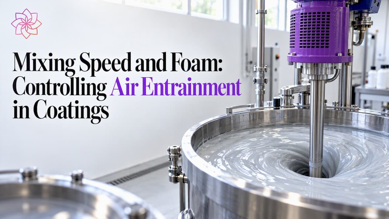
Mixing speed influences foam through two competing effects: higher impeller or blade speed delivers more shear, which improves wetting, deagglomeration and homogenization, but it also pulls more air into the batch and breaks that air into smaller bubbles that are harder to release. The practical objective is therefore not the lowest speed or the highest speed, but the highest speed at which the surface stays closed and the entrained air remains manageable, combined with a defoamer matched to the system. This article sets out the mechanisms, a selection procedure, a testing and scale-up approach, and the role of defoamer chemistry for coating, adhesive, ink and composite formulators.
TL;DR
- Foam requires mechanical energy and a stabilizing surfactant; in a formulation, wetting agents, dispersants and emulsifiers supply the stabilization, while the mixer supplies the energy.
- Foam problems are driven less by rpm alone than by tip speed, vortex depth, impeller position and liquid level, so adjust geometry and addition order before reducing speed.
- Select speed in steps: raise it until the vortex draws air, back off to the point where the surface is closed, and confirm dispersion quality by fineness of grind, not by appearance.
- Verify every change by density (weight per gallon) and film appearance, and scale on tip speed and power per volume, not on rpm.
- A correctly selected defoamer, added at the right stage, widens the usable speed window; an overdosed or incompatible one produces craters and haze.
Foam is a dispersion of gas in a liquid, and its formation depends on two conditions. The first is energy input: mechanical energy is needed to generate foam, while surfactants promote its production by stabilizing the liquid films. The second is persistence: foam survives only as long as the lamellae between bubbles resist thinning and rupture. In consumer foams such as shampoo and beer, surfactant molecules coating the bubbles stabilize the foam by hindering coalescence.
In a coating or adhesive batch, the same principle applies, with more stabilizers present than in most systems. Dispersants, wetting agents, associative thickeners, emulsifiers, and residual surfactants in resin emulsions all adsorb at the air-liquid interface. Pigments and fillers add a further contribution: particles with partially wetted surfaces can anchor at bubble walls, and a rising viscosity slows drainage and bubble rise. The result is that a formulation that is stable and well dispersed is, almost by definition, also well equipped to hold foam.
Two foam populations are usually distinguished in practice:
- Surface foam, a layer of large bubbles on top of the batch. It is visible, usually collapses after mixing stops, and is mainly a handling and fill-volume issue.
- Entrained air (microfoam), fine bubbles dispersed through the bulk. It is often invisible during mixing, raises viscosity apparent behavior, lowers density, and later appears as pinholes, craters, bubbles or reduced gloss in the dried film.
The second population is the commercially important one, because it determines defect rates downstream.
How mixing speed affects foam and air entrainment
Speed acts on foam through several distinct mechanisms, and separating them explains why a simple rpm reduction sometimes fails.
Vortex formation and surface entrainment
At low viscosity, an axial or radial impeller near the surface produces a vortex. As speed increases, the vortex deepens until it reaches the impeller or the surface becomes turbulent enough to fold air into the liquid. This threshold, often called the onset of air entrainment, depends on impeller diameter, liquid depth above the impeller, vessel geometry and the presence of baffles. Once crossed, the air input rises steeply, not proportionally, with further speed increases.
Shear-induced bubble breakup
Entrained air does not remain as large bubbles when the shear field is intense. High local shear near the blade breaks bubbles into smaller ones. Small bubbles rise slowly, since rise velocity falls with the square of bubble diameter in a viscous liquid, and they are stabilized more effectively by adsorbed surfactant. A batch run at high tip speed after air has entered can therefore hold more microfoam than one run slower, even though the slower batch may have looked more turbulent.
Viscosity and the dispersion stage
During the grind or dispersion stage, viscosity is deliberately high so that shear transfers efficiently to the agglomerates. In this regime air that is incorporated cannot escape, because bubble rise is retarded. Air entrained here is the hardest to remove later. During letdown, viscosity falls, bubbles move more freely, but surfactant-rich resin and additive solutions are added, which raises stabilization. Each stage has its own failure mode, which is why one fixed speed rarely suits the full cycle.
Tip speed, not rpm
Rpm describes shaft rotation, whereas the shear a particle experiences relates to blade tip speed, which scales with both rpm and blade diameter. Two dispersers at the same rpm with different blade diameters produce different tip speeds, different shear and different air entrainment. Quoting speed in rpm without diameter gives a number that cannot be transferred between equipment.
Mixer geometry and operating practice that reduce foam before speed is changed
Several adjustments lower air entrainment without sacrificing shear, and they should be evaluated before accepting a lower speed.
- Impeller submergence. Keep the blade well below the surface so that the vortex does not reach it. A common starting point for high-speed dispersers is a blade diameter relative to vessel diameter and a liquid height that keep the characteristic donut flow pattern, with the blade positioned off the bottom by roughly one blade diameter. Exact ratios should come from the equipment manufacturer.
- Liquid level and fill volume. A low liquid level over the blade invites vortexing. Fill volume should leave freeboard for the foam that does form.
- Order of addition. Add powders slowly at the edge of the vortex, below the surface if the equipment permits, rather than dropping them from height. Dry powders carry adsorbed air into the batch. Add surfactant-rich components after the high-shear phase where the formulation allows.
- Impeller type. Sawtooth blades, pitched-blade turbines, and low-shear anchors differ in how much air they pump. Matching the blade to the stage (dispersion versus letdown) is often more effective than changing speed.
- Baffling and off-center mounting. Breaking the swirl suppresses the deep central vortex while preserving bulk flow.
- Liquid-surface protection. Return lines and charging pipes should discharge below the liquid surface, not above it.
- Vacuum or pressure. Where equipment allows, mixing under reduced pressure removes air during or after the high-shear phase, particularly useful for adhesives and composite resins.
Selecting mixing speed for a specific formulation
The following procedure gives a defensible speed setting using bench equipment that is available in most laboratories.
Step 1: Define the quality criteria
Set measurable targets before changing speed: fineness of grind (Hegman or equivalent), viscosity at a defined shear rate, density against the theoretical value, and film appearance on a drawdown. Speed is then tuned against these, not against appearance of the batch in the vessel.
Step 2: Establish the air entrainment threshold
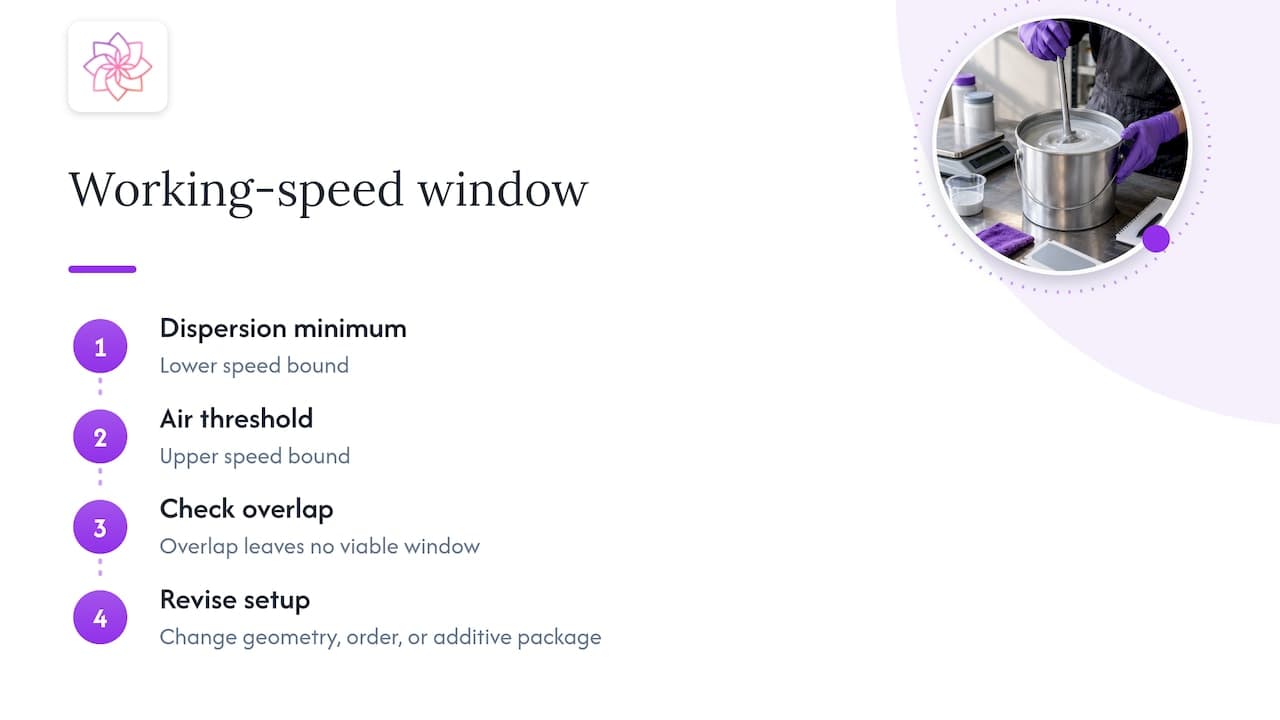
Start at a low speed with correct submergence and increase in increments, holding each for a fixed time. Record the speed at which the vortex first reaches the blade or the surface begins to fold. This is the upper bound for the current geometry and level.
Step 3: Find the minimum speed for dispersion
At each increment, take a sample and measure fineness of grind and viscosity development over time. Many pigment systems reach a plateau in which additional energy yields little further deagglomeration. Speed above the plateau adds air and heat but no benefit.
Step 4: Choose the operating window
The working speed lies between the minimum for dispersion and the entrainment threshold. If the two overlap, with no window, geometry, addition order or the dispersant and defoamer package needs revision rather than the speed.
Step 5: Define speeds per stage
Record separate speeds for powder incorporation, high-shear dispersion, and letdown. A common pattern is slow incorporation, higher speed once the powders are wetted, and a reduced speed for letdown and additive addition.
| Stage | Typical objective | Foam risk | Speed approach |
|---|---|---|---|
| Powder incorporation | Wet pigment and filler without carrying air | Air carried with powder | Low speed, controlled addition |
| High-shear dispersion | Deagglomeration | Microfoam trapped in high viscosity | Highest speed that keeps the surface closed |
| Letdown | Homogenize with resin and additives | Surfactant-driven surface foam | Reduced speed, subsurface additions |
| Final adjustment and deaeration | Release entrained air | Residual microfoam | Slow stirring, optional vacuum |
Reducing foam without losing dispersion quality
Reducing speed is the simplest response and frequently the least effective, because it cuts the shear that the dispersion depends on. A more reliable hierarchy is as follows.
- Correct geometry and level, as above.
- Review the surfactant load. Excess wetting agent or dispersant beyond the pigment surface demand remains free in the liquid and stabilizes foam. Dosage optimization often lowers foam and cost simultaneously.
- Select a defoamer suited to the system and add it at the stage where the air-liquid interface needs it.
- Only then reduce speed, and by the smallest increment that restores a closed surface.
The role of defoamers
A defoamer works by entering the bubble film, spreading across it and destabilizing the lamella so that bubbles coalesce and release. To perform that function it must be sufficiently incompatible with the medium to reach the interface, yet sufficiently dispersed to be present throughout the batch. Too compatible, and it is ineffective. Too incompatible or too coarsely dispersed, and it remains as droplets that cause craters, fisheyes or loss of gloss.
Two broad chemistries are used:
- Silicone-based defoamers offer strong knock-down and persistence at low dosage, particularly in waterborne systems, but carry a risk of surface defects and recoat problems where silicone contamination is unacceptable.
- Non-silicone defoamers (mineral oil, polymeric and other organic types) avoid silicone-related defects and are preferred in systems sensitive to recoatability or adhesion, sometimes with a higher dosage requirement.
ASTRA Chemical supplies both categories: ASTRA DF® for silicone-based defoaming and ASTRA DF NS® for non-silicone applications. The choice depends on binder type, recoat requirements, substrate and the stage at which foam appears.
Timing and dosage of the defoamer
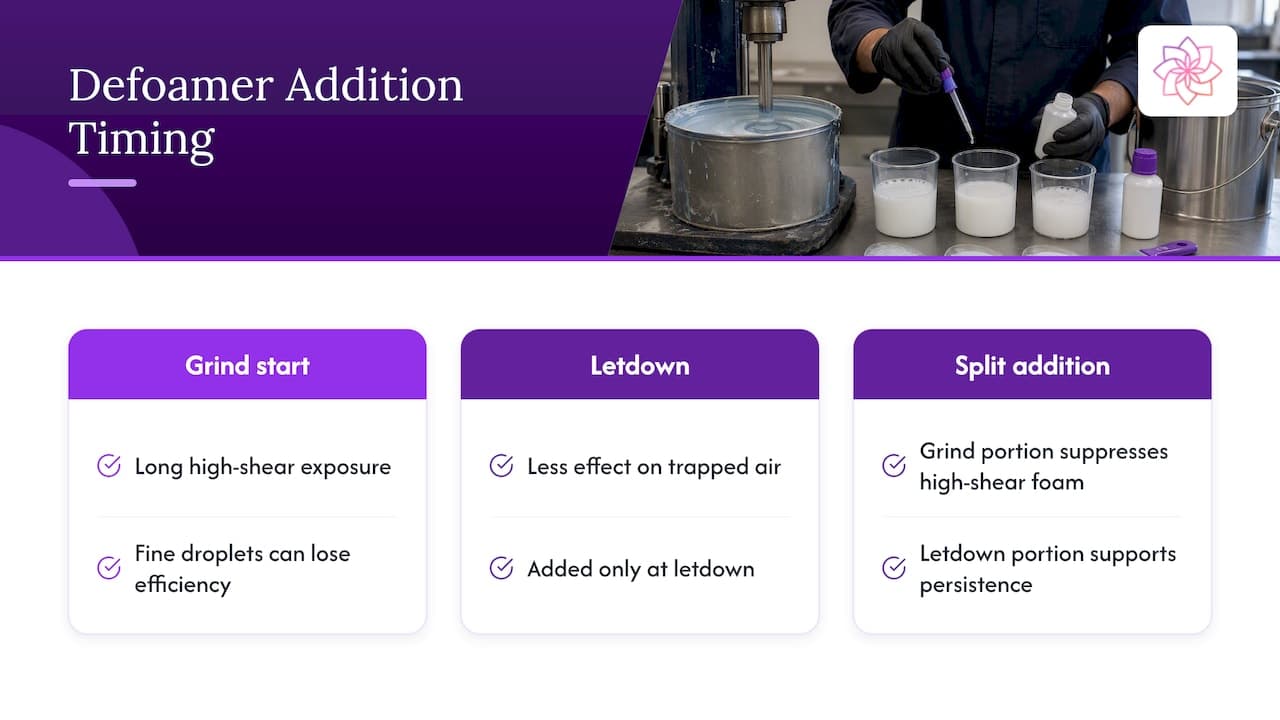
Timing matters as much as selection. A defoamer added at the start of the grind is exposed to high shear for a long time and can be dispersed into very fine droplets that lose efficiency, while one added only at letdown has less effect on air trapped during dispersion. Many formulators split the addition: a portion in the grind to suppress foam during high shear and a portion at letdown for persistence. Dosage should be set by a ladder study, since overdosing is a common cause of defects that are attributed incorrectly to the resin or the substrate.
Testing changes and scaling up
A speed or defoamer change is validated by data, and the same data guide scale-up.
Laboratory tests
- Density (weight per gallon) cup: compares measured density with the theoretical density; the deficit indicates entrained air volume. This is the quickest quantitative measure of microfoam.
- Foam height and collapse time: mixing a fixed volume at fixed speed and time in a graduated vessel, and recording initial foam height and the time to collapse, supports comparisons between defoamer candidates.
- Drawdown and film inspection: applied at controlled thickness, with inspection for craters, pinholes and gloss loss after cure.
- Viscosity before and after deaeration: a rise on standing or a drop after deaeration points to air contributing to apparent rheology.
- Storage stability: defoamer efficiency can decline on ageing, so retest after heat-age cycles.
Scale-up principles
Laboratory success does not transfer by matching rpm. A sound approach is to:
- Match tip speed first for dispersion-driven steps, then verify the shear result by fineness of grind at scale.
- Check geometric similarity: blade-to-vessel diameter ratio, liquid height and blade clearance. Where it cannot be maintained, adjust speed to preserve the dispersion result and re-establish the entrainment threshold.
- Account for batch size and heat. Larger batches retain heat from high-shear work, which lowers viscosity, changes defoamer partitioning and can shift the foam balance.
- Re-run the density and drawdown tests on the first production batches, and adjust defoamer dosage at scale rather than assuming laboratory dosage transfers.
- Document the speeds, geometry, addition order and times so that the process is reproducible across shifts and sites.
Perspective: what mixing-speed problems usually trace back to
In our work with coating, adhesive and ink formulators, the reported complaint is usually foam, but the cause is often an interaction: a dispersant level set above the pigment demand, a blade too close to the surface, a defoamer added at a stage where it is sheared away, or a laboratory speed carried to production without regard to tip speed. Treating the symptom by lowering rpm tends to move the problem into the dispersion quality, producing coarse grind, color development loss and a request for more additive.
Our approach is to treat dispersant and defoamer as one system and to qualify them together, in the customer's own resin and pigment, at the customer's own equipment settings. That means a dosage ladder rather than a single recommended figure, a split defoamer addition where the process calls for it, and a documented operating window for each stage. The aim is comparable performance to premium additives at a lower total cost in use, which is realized through optimized dosage and batch consistency, and not through a higher loading.
— Astra R&D Team
Qualifying a dispersant and defoamer package
Formulators who want to widen their speed window can evaluate the ASTRA product range with laboratory-backed qualification and technical support. The ASTRA DISP® dispersant line addresses pigment wetting and stabilization, while the defoamer lines above address air release. The full range, including rheology modifiers and functional additives, is listed on the ASTRA CHEMICAL products page, where sample requests and technical consultations can be arranged for a specific formulation.
FAQ
What mixing speed prevents foam in a coating batch?
No single rpm applies, because the threshold depends on blade diameter, submergence, liquid level, viscosity and the surfactants present. The workable speed is the highest one at which the surface stays closed and dispersion targets such as fineness of grind are still met. It is found by stepwise testing on the actual formulation and equipment.
Does a higher mixing speed always create more foam?
Generally more energy input produces more foam, but the relationship is not linear. Below the air entrainment threshold, added speed creates little foam, and above it the air input rises sharply. Blade position, baffling and liquid level shift that threshold substantially.
Should a defoamer be added before or after high-speed mixing?
Often both. A portion added in the grind controls foam during high shear, and a portion at letdown supplies persistence once surfactant-containing components are added. The split should be confirmed with density and drawdown testing, as early addition at high shear can lower defoamer efficiency.
When is a non-silicone defoamer preferable?
A non-silicone type is generally chosen when recoatability, adhesion or crater sensitivity makes silicone contamination a risk. Silicone types are often preferred for strong knock-down at low dosage. The decision should be validated on a drawdown in the actual system.
How is the air content of a batch measured?
The most accessible method is comparing the measured density in a weight per gallon cup with the theoretical density of the formulation. A lower measured value indicates entrained air. Film inspection for pinholes and craters confirms the effect on the finished product.
Sources
Testing additives for this application?
Send us your current formulation challenge and our technical team will recommend an ASTRA product package for lab screening.